
Free Shipping

Money Back Guarantee
0800 048 1057
Currency

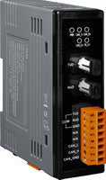
I-2533 CAN-Bus to Fibre Optic Bridge
- £198.00
- £198.00
- (-0%)
- Unit price
- per
CAN bus to Fibre Optic Bridge, allows for different baud rates on each CAN network, increasing of CAN transmission distance and improved error handling.
Subtotal:
£198.00
Couldn't load pickup availability
Free Shipping
Free standard shipping on orders over £500
Free Returns
30 Day Money Back Guarantee


Description
xThe I-2533 is a local CAN bridge used to establish a connection between two CAN bus system via a fibre-optic connection. The I-2533 is especially designed for converting the electrical CAN bus signal to fiber optic cables and has three additional features over the standard I-2532 CAN-Fibre converter.
- Transmission Distance is not reduced due to the CAN Baud rate, meaning that the total network distance can be extended.
- A bus error on one CAN network will not affect the operation of another CAN network.
- Two CAN networks can communicate with each other using different CAN baud rates for increased flexibility. A utility program is provided with the I-2533 to configure the user-defined baud rate and meassge filter configuration. NOTE: When the I-2533 is used on two CAN networks with different CAN baud rate, it may be useful to reduce the bus loading on the network which has a low baud rate.
Features
xNote: ICP have verified to drive 100 CAN nodes at the same time via one CAN port of I-2533.
- Support both CAN 2.0A and CAN 2.0B specification
- Fully compatible with the ISO 11898-2 standard
- Rotary switch for CAN baud rate configuration
- Up to 100 CAN nodes on the CAN channel (*Note)
- Transmission distance up to 2 km at any CAN baud rate
- Provides the 512-record CAN Tx buffer and 512-record CAN Rx buffer
- Allow user-defined baud rate
- Software utility tool for message filter configuration
- Fibre Port: ST (Multi-mode)
- Broken line detection for fiber cable
Specifications
x| CAN Interface | |
| Connector | Screwed terminal block (CAN_GND, CAN_L, CAN_H) |
| Baud Rate (bps) | 10 k ~ 1 M |
| Transmission Distance (m) | Depend on baud rate |
| Terminator Resistor | Switch for 120Ω terminator resistor |
| Isolation | 3000 VDC for DC-to-DC, 2500 Vrms for photo-couple |
| Specification | ISO-11898-2, CAN 2.0A and CAN 2.0B |
| Time Delay | 120us max (CAN to fiber or fiber to CAN) |
| Fiber Interface | |
| Connector | ST (Multi-mode) |
| Wave Length | 850 nm |
| Fiber Cable | 50 / 125 μm , 62.5 / 125 μm, 100 / 140 μm (62.5 / 125μm is recommended) |
| Transmission Distance (m) | 2 km max (in 62.5 / 125 μm fiber cable) at any CAN baud rate |
| LED | |
| Round LED | PWR LED, CAN_Tx LED, CAN_Rx LED, CAN_Err LED, FB_Err LED |
| Power | |
| Power supply | Unregulated +10 ~ +30 VDC |
| Protection | Power reverse polarity protection, Over-voltage brown-out protection |
| Power Consumption | 3 W |
| Mechanism | |
| Installation | DIN-Rail |
| Dimensions | 32.3mm x 77.5mm x 99.0mm (W x L x H) |
| Environment | |
| Operating Temp. | -25 ~ 75 ? |
| Storage Temp. | -30 ~ 80 ? |
| Humidity | 10 ~ 90% RH, non-condensing |
Technical
xApplications
x- Control System
- Building Automation
- Factory Automation
- Distributed data acquisition
Related Products
Example product title
- £198.00
- £198.00
- (-0%)
- Unit price
- per
Example product title
- £198.00
- £198.00
- (-0%)
- Unit price
- per
Example product title
- £198.00
- £198.00
- (-0%)
- Unit price
- per
Example product title
- £198.00
- £198.00
- (-0%)
- Unit price
- per
Example product title
- £198.00
- £198.00
- (-0%)
- Unit price
- per
Example product title
- £198.00
- £198.00
- (-0%)
- Unit price
- per
Example product title
- £198.00
- £198.00
- (-0%)
- Unit price
- per
Example product title
- £198.00
- £198.00
- (-0%)
- Unit price
- per
Example product title
- £198.00
- £198.00
- (-0%)
- Unit price
- per
Example product title
- £198.00
- £198.00
- (-0%)
- Unit price
- per
Recently Viewed Products
Example product title
- £198.00
- £198.00
- (-0%)
- Unit price
- per
Example product title
- £198.00
- £198.00
- (-0%)
- Unit price
- per
Example product title
- £198.00
- £198.00
- (-0%)
- Unit price
- per
Example product title
- £198.00
- £198.00
- (-0%)
- Unit price
- per
Example product title
- £198.00
- £198.00
- (-0%)
- Unit price
- per
Example product title
- £198.00
- £198.00
- (-0%)
- Unit price
- per
Example product title
- £198.00
- £198.00
- (-0%)
- Unit price
- per
Example product title
- £198.00
- £198.00
- (-0%)
- Unit price
- per
Example product title
- £198.00
- £198.00
- (-0%)
- Unit price
- per
Example product title
- £198.00
- £198.00
- (-0%)
- Unit price
- per
- Choosing a selection results in a full page refresh.