
Free Shipping

Money Back Guarantee
0800 048 1057
Currency
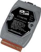

I-7530A-MR Modbus RTU to CAN Converter
- £270.00
- £270.00
- (-0%)
- Unit price
- per
Modbus RTU (RS232/RS485) to CAN converter module
Subtotal:
£270.00
Couldn't load pickup availability
Free Shipping
Free standard shipping on orders over £500
Free Returns
30 Day Money Back Guarantee


Description
x The I-7530A-MR is designed to enable communication between RS-232/485/422 devices and the CAN devices. It supports three communication modes: “Normal”, “Modbus RTU”, “Pair-connection”.
In the Normal mode, the I-7530A-MR is designed to unleash the power of CAN bus via RS-232/485/422 communication method. It accurately converts ASCII format messages and CAN messages between RS-232/485/422 and CAN networks. This mode let you to communicate with CAN devices easily from any PC or programmable devices with RS-232/485/422 interface.
In Modbus RTU mode, it allows a Modbus RTU master to communicate with CAN devices on a CAN network. The following figure shows the application architecture of this mode.

Features
x- RoHS Design
- Fully compatible with ISO 11898-2 standard
- Programmable CAN bus baud rate from 10 kbps to 1 Mbps or user-defined baud rate
- Supports CAN bus acceptance filter configuration
- Supports firmware update via RS-232
- Utility tool provided for module setting and CAN bus communication testing
- Built-in jumper to select 120Ω terminator resistor
- CAN buffer: 128 data frames ; UART buffer: 256 bytes
- Power, data flow and error indicator for CAN and UART status
- Hardware Watchdog design
- Converts CAN message to specific ASCII command string (Normal mode)
- Converts specific ASCII command string to CAN message (Normal mode)
- Provides transparent communication between the RS-232/485/422 devices via CAN bus (Pair-connection mode)
- Supports function code 0x03/0x04/0x10 of Modbus RTU command for reading and writing CAN message (Modbus RTU mode)
UTILITY
- CAN bus Baud Rate configuration
- CAN acceptance filter configuration
- CAN 2.0A or 2.0B specific selection
- RS-232/485/422 baud rate and data format configuration
- RS-232/485/422 communication with checksum function selection
- Communication mode setting
- Easily transmit/receive CAN messages
Specifications
x| Hardware | |
| EEPROM | 16 KB (for system information), 10,000,000 erase/write cycles |
| CAN Interface | |
| Transceiver | NXP 82C250 |
| Connector | 9-pin male D-Sub (CAN_L, CAN_H, N/A for others) |
| Channels | 1 |
| Baud Rate (bps) | 10 k, 20 k, 50 k, 100 k, 125 k, 250 k, 500 k, 800 k and 1 M (allow user-defined baud rate) |
| Protection | 3000VDC power protection and 3750Vrms photo-couple isolation on CAN side |
| Terminator Resistor | Selectable 120Ω terminator resistor by jumper |
| Support Protocol | ISO-11898-2, CAN 2.0A and CAN 2.0B |
| Pin Assignment | C.I.A. DS-102 (CAN_H=7, CAN_L=2) |
| UART Interface | |
| COM | RS-232/RS-485/RS-422 (can’t be used simultaneously) |
| Connector | 14-pin terminal connector RS-232 : TxD, RxD, GND RS-422 : TxD+, TxD-, RxD+, RxD- RS-485 : DATA+, DATA- |
| Baud Rate (bps) | 300,600,1200, 2400, 4800, 9600, 19200, 38400, 57600, 115200, 230400 |
| Protection | 3000VDC power protection and 2500Vrms photo-couple isolation on UART side |
| LED | |
| Round LED | PWR/CAN/UART |
| Power | |
| Power supply | +10 ~ +30 VDC |
| Power Consumption | 1.5 W |
| Dip Switch | Init (Firmware Update, Module Configuration)/Normal (Firmware Operation) |
| Mechanism | |
| Installation | DIN-Rail |
| Dimensions | 72mm x 118mm x 35mm (W x L x H) |
| Environment | |
| Operating Temperature | -25 ~ 75 ? |
| Storage Temperature | -30 ~ 80 ? |
| Humidity | 10 ~ 90% RH, non-condensing |
Applications
x- Control System
- Building Automation
- Factory Automation
- Distributed data acquisition
Related Products
Example product title
- £270.00
- £270.00
- (-0%)
- Unit price
- per
Example product title
- £270.00
- £270.00
- (-0%)
- Unit price
- per
Example product title
- £270.00
- £270.00
- (-0%)
- Unit price
- per
Example product title
- £270.00
- £270.00
- (-0%)
- Unit price
- per
Example product title
- £270.00
- £270.00
- (-0%)
- Unit price
- per
Example product title
- £270.00
- £270.00
- (-0%)
- Unit price
- per
Example product title
- £270.00
- £270.00
- (-0%)
- Unit price
- per
Example product title
- £270.00
- £270.00
- (-0%)
- Unit price
- per
Example product title
- £270.00
- £270.00
- (-0%)
- Unit price
- per
Example product title
- £270.00
- £270.00
- (-0%)
- Unit price
- per
Recently Viewed Products
Example product title
- £270.00
- £270.00
- (-0%)
- Unit price
- per
Example product title
- £270.00
- £270.00
- (-0%)
- Unit price
- per
Example product title
- £270.00
- £270.00
- (-0%)
- Unit price
- per
Example product title
- £270.00
- £270.00
- (-0%)
- Unit price
- per
Example product title
- £270.00
- £270.00
- (-0%)
- Unit price
- per
Example product title
- £270.00
- £270.00
- (-0%)
- Unit price
- per
Example product title
- £270.00
- £270.00
- (-0%)
- Unit price
- per
Example product title
- £270.00
- £270.00
- (-0%)
- Unit price
- per
Example product title
- £270.00
- £270.00
- (-0%)
- Unit price
- per
Example product title
- £270.00
- £270.00
- (-0%)
- Unit price
- per
- Choosing a selection results in a full page refresh.