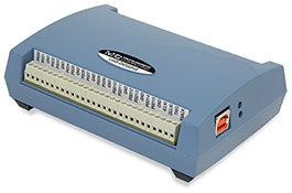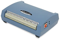

USB-DIO32HS 32-Bit High-Speed Digital I/O Device
- £480.00
- £480.00
- (-0%)
- Unit price
- per
USB-based 32-bit high-speed digital I/O device, with independent input and output scan clocks, hardware and software triggering, and pattern detection / generation
Subtotal:
£480.00
Couldn't load pickup availability
Free Shipping
Free standard shipping on orders over £500
Free Returns
30 Day Money Back Guarantee
Description
x Summary
The USB-DIO32HS provides 32 bits of high-speed digital I/O, and features independent input and output scan clocks, hardware and software triggering, and pattern detection/generation.
Digital I/O
The 32 DIO bits are available as two 16-bit ports that are bit-configurable for input or output. Each port is configured independently, so both software polling and hardware scanning operations can be performed at the same time.
When performing software polling, the port can contain any combination of input or output bits. When performing hardware-paced output scans, all bits in the port must be set for output. For input scans, however, the current state of any bits in the port that are configured for output are read.
Digital Output Scanning
Either port can output a 16-bit digital pattern. The pattern is updated at a rate up to 8 MS/s, and clocked using the output scan clock. Use both ports to output a 32-bit digital pattern. Data from one port is read and stored in the FIFO buffer until the second port is read. Both ports are output simultaneously on the rising edge of the next pacer clock signal.
Data Transfer
The USB-DIO32HS uses a delay between the output scan clock and the data transfer pin, which allows an external device that is receiving the data to know that the data is stable at that point, and ensures a coherent data transfer between devices.
Pull-Up/Down Configuration
The DIO bits can be pulled up to 5 V or down to 0 V through 47 kO resistors via onboard jumpers.
Clock I/O
Users can pace input scanning operations with the onboard input scan clock or with an external signal. The input clock frequency is 8 MHz, maximum.
A duty cycle of 50% is maintained when the internal input clock paces operations. When using an external clock, the signal is output immediately after the external clock input is received.
Triggering
Digital and pattern triggering are supported.
The TRIG pin is used for external TTL-level triggering, and can be used to trigger input or output scans. Trigger latency is less than 1 µs. The trigger mode is software-selectable for edge or level sensitive, and high or low logic.
Either digital port can be used for pattern triggering. A scan is triggered when a specified pattern is detected. Specific bits can be masked or ignored. Trigger latency is 1 scan clock period. You can input or output a digital pattern under the timing control of a clock signal.
Features
x32 bits of bidirectional TTL digital I/O
Pattern detection and generation
Input scan rate up to 8 MS/s
Update rate up to 8 MS/s
250 µS (typical) response time for single value read/write
Independent input and output scan clocks
24 mA source, 10 mA sink output current
External trigger and clock inputs
Board-Only OEM Version Available with header connectors (no case, CD, or USB cable included)
Software
TracerDAQ® for acquiring and displaying data and generating signals
Universal Library includes support for Visual Studio® and Visual Studio® .NET,
including examples for Visual C++®, Visual C#®, Visual Basic®, and Visual Basic® .NET
Universal Library for Android™ includes support and examples for the Android 3.1
platform (API level 12) and later
DASYLab® and NI LabVIEW™ drivers
InstaCal™ software utility for installing, configuration, and testing
Supported Operating Systems: Windows® 8/7/Vista®/XP, 32-bit or 64-bit;
Android 3.1 (API level 12) and later; Linux®
Specifications
xApplications
xRelated Products
Example product title
- £480.00
- £480.00
- (-0%)
- Unit price
- per
Example product title
- £480.00
- £480.00
- (-0%)
- Unit price
- per
Example product title
- £480.00
- £480.00
- (-0%)
- Unit price
- per
Example product title
- £480.00
- £480.00
- (-0%)
- Unit price
- per
Example product title
- £480.00
- £480.00
- (-0%)
- Unit price
- per
Example product title
- £480.00
- £480.00
- (-0%)
- Unit price
- per
Example product title
- £480.00
- £480.00
- (-0%)
- Unit price
- per
Example product title
- £480.00
- £480.00
- (-0%)
- Unit price
- per
Example product title
- £480.00
- £480.00
- (-0%)
- Unit price
- per
Example product title
- £480.00
- £480.00
- (-0%)
- Unit price
- per
Recently Viewed Products
Example product title
- £480.00
- £480.00
- (-0%)
- Unit price
- per
Example product title
- £480.00
- £480.00
- (-0%)
- Unit price
- per
Example product title
- £480.00
- £480.00
- (-0%)
- Unit price
- per
Example product title
- £480.00
- £480.00
- (-0%)
- Unit price
- per
Example product title
- £480.00
- £480.00
- (-0%)
- Unit price
- per
Example product title
- £480.00
- £480.00
- (-0%)
- Unit price
- per
Example product title
- £480.00
- £480.00
- (-0%)
- Unit price
- per
Example product title
- £480.00
- £480.00
- (-0%)
- Unit price
- per
Example product title
- £480.00
- £480.00
- (-0%)
- Unit price
- per
Example product title
- £480.00
- £480.00
- (-0%)
- Unit price
- per
- Choosing a selection results in a full page refresh.

